Exercising slow
All questions about motion or speed are only complete with an appropriate frame of reference.
Exercising slow at 50.8357°N & 4.3615°E,
I find myself in between projects, exploring our perception of time in preparation of a new installation.
Contents
Gearbox
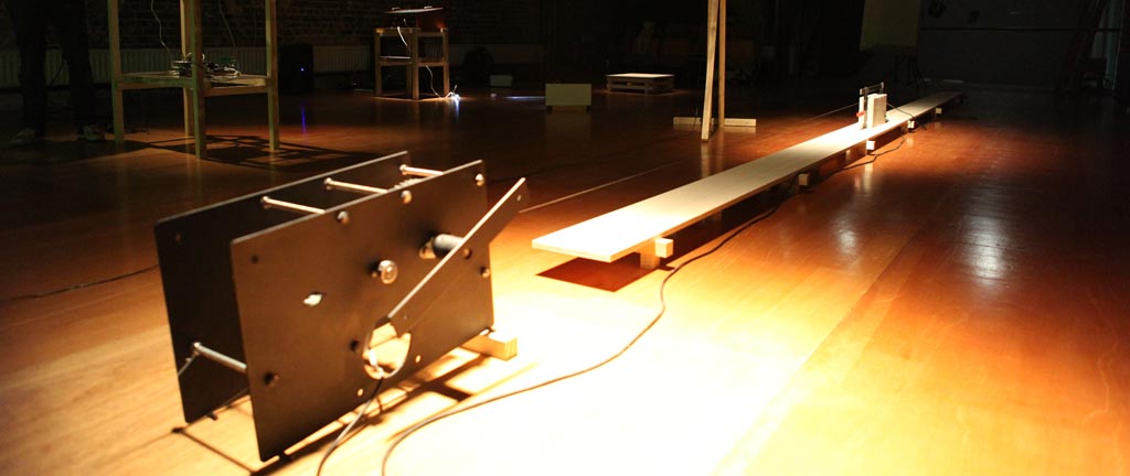
The gearbox consists of several PolyEtheleen water cut gears driven by an Ametek surplus DC motor controlled by an arduino + motorshield.
AMETEK 38VDC 900 RPM MOTOR - 900 RPM AMETEK, #965922-101. Permanent magnet DC motor rated 38 VDC nominal. Reversible, ball bearing. Max. rated rpm is 1300 max. Armature current before permanent demagnetizationis 12 amps. Torque constant is 50 oz-in per amp. Terminal resistance 20ohms +-20%. Voltage constant is 37 VDC per 1000 rpm. When tested on 38 VDC, we recorded the following data: No-load spedd 1100 rpm @ 0.260 amp. With a 100 oz-in load the shaft speed was 900 rpm @ 2.3 amps. When tested as a generator at 1000 rpm, the output was 5.8 amps @ 12 VDC. Shaft: 5/8" dia. X 1-5/16" long. The opposite end of the shaft has a turned down diameter and a flat mounting area with two sets of tapped holes. This was probably originally intended for an encoder or tachometer mounting. This shaft has an outside dia. of 3/16" and is approx. 3/8" long. We do not have the encoders whtat were mounted on this motor, but suitable encoders are probably available from encoder suppliers if required. The motor has five #10x32 tpi tapped mounting holes on the shaft end of the motor body. Electrical connections are via 3-1/2" long flexible wires. Dimensions: 4" dia. X 4-1/2" long (excluding shafts). $74.50 Ea. MD548
Working with module 4 gears which are water cut out of PE.
All about measurements of module 4 metric gears : http://www.metrication.com/engineering/gears.html
concrete block 19/39/9 cm 8.6 kg
birch platform 25.5 cm
nadine platform 15 meters long
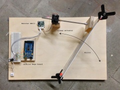
Mirror setup
Code
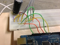
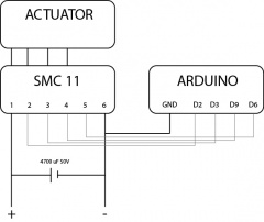
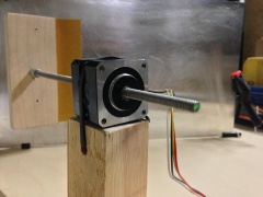
Here's the code I used to drive a linear actuator hooked up to the Nanotec SMC11 stepper driver board.
/* Code to control the Nanotec SMC11 stepper board from an arduino
*/

int EnPin = 2;      // Enable low = active, high = disabled
int DirPin = 3;      // Direction low = active, high = disabled
int ClkPin = 9;   // CLK
int sensorPin = A0;    // select the input pin for the potentiometer
int sensorValue = 0;  // variable to store the value coming from the sensor
int CurrPin = 6; // Current enable pin
int incomingByte;
int ctrl = 0;


void setup()
{
  pinMode(EnPin, OUTPUT);   // sets the pin as output
  pinMode(DirPin, OUTPUT);   // sets the pin as output
  pinMode(ClkPin, OUTPUT);   // CLK
  digitalWrite(EnPin, LOW);
  digitalWrite(DirPin, LOW);
  digitalWrite(CurrPin, HIGH);
  Serial.begin(9600);


}

void loop()
{
 // Serial commands to arduino F = Forward, B = Backwards, S = Stop motor
    if (Serial.available() > 0) {

    incomingByte = Serial.read();
        if ( incomingByte == 'F'){
            ctrl = 1;
            //Serial.print("F");
        }
        if ( incomingByte == 'B'){
            ctrl = 2;
            //Serial.print("B");
        }
        if ( incomingByte == 'S'){
            ctrl = 0;
            //Serial.print("S");
        }
    }


    switch (ctrl) {
    case 1:
      //do something when var equals 1
      //Serial.print("1");
      forward();
      break;
    case 2:
      //do something when var equals 2
      //Serial.print("2");
      backwards();
      break;
    case 0:
      stops();
  }


}

void run()
{

  digitalWrite(ClkPin, LOW); //active
  delayMicroseconds(200);
  digitalWrite(ClkPin, HIGH);//disabled
  delayMicroseconds(400);

}

void forward()
{
  digitalWrite(EnPin, LOW);
  delayMicroseconds(150);
  digitalWrite(DirPin, LOW);
  delayMicroseconds(150);
  run();
}

void backwards()
{
  digitalWrite(EnPin, LOW);
  delayMicroseconds(150);
  digitalWrite(DirPin, HIGH);
  delayMicroseconds(150);
  run();

}

void stops(){
  digitalWrite(EnPin, HIGH);
  delayMicroseconds(150);

}
xbee config
Using moltosenso network manager iron to configure Xbee modules. Using Xbee Pro series 2
http://nl.wikipedia.org/wiki/Circadiaan_ritme
http://nl.wikipedia.org/wiki/Tijdsperceptie
minimal music. 57210982, http://en.wikipedia.org/wiki/Minimal_music, stasis
